Mechanics
MP-CNC mechanics
The MP-CNC uses a single rod for its axis, both for support of the Z and X axis assembly. These rods are the basic structural elements.

Photo by V1 Engineering, click image for link.
Not visible in the picture above are the belts that are used to move the Z assembly. They can however be seen in other pictures at the site. I wonder if the design initially used friction drives and belts were added later.
Axis support
The main problem I foresee when using this type of setup is sag. Remember that I would like to build a CNC with 2000mm of workable area in the X-axis. A rod of that length would noticeably sag. Probably more than 1 or 2 mm, but at the very least more than the wanted accuracy of 0,1mm.
To avoid that I will be using the previously mentioned SBR12, SBR16 or SBR20 rails.
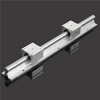
These rails usually come with two sliders that can be used to mount the other axis on. The sliding construction is quite firm and can be used to put considerable force on the tool.
Belts or linear ball-screws?
Using belts is a common way for cheap CNC machines. The more expensive machines use linear ball-screws. These allow much more force to be brought upon the tool and as such allow for greater precision on hard materials and/or higher speeds.
Using a belt on a 2000mm axis feels like a recipe for disaster. Maybe it won’t be a problem at all, but I simply do not like trying. Hence I will be using linear ball-screws.
These look like this:
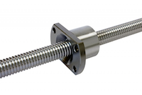
It is hard to see in this picture, but if you google ‘ball-screw’ then you can find some close ups that show the difference between a lead-screw and a ball-screw. A ball-screw is a kind of ball-bearing mounted on a threaded rod. A lead-screw is a ‘normal’ screw that is optimised for use as a precision stage driver. However a lead-screw is less efficient, cannot transfer as much force, and will likely develop slop over time. The lead-screw is cheaper, but imo the ball-screw more than justifies its higher price.
Stage design
Unfortunately I do not have a picture for this, so bear with me as I try to describe how the X and Y-axis will look like…
The SBR16 rods will be mounted on either side of a long table. A bridge will cross from one to the other, mounted on the sliders. Above or to the side of the rod, the ball-screw will be mounted and fixed to the bridge. Then when the screw is turned, the ball-bearing will push or pull the bridge along the X axis.
The ball-screw is mounted on just one side (initially). The rigidity of the X-bridge should be enough to prevent torsion forces from deflecting the tool. If necessary, another ball-screw can be added to the other side, with its own stepper motor.
The X-bridge will receive a similar structure for the Y-bridge. And the Y-bridge will receive a Z-bridge. However The Z-bridge has only limited travel and there are ready build units at a decent price, so it does not make sense to build this myself.