XYZ Design
In the first post I wrote that I wanted a CNC-able area of at least 2 meters (X) by 40 centimers (Y). (2000mm x 400mm)
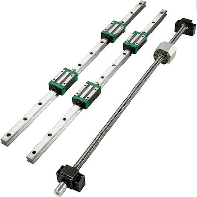
Unfortunately I was unable to find a ball-screw with a length of 2000mm for an affordable price. The ball-screw itself is not even that expensive, its the shipping that kills the idea. Some suppliers charge more for shipping than the ball-screw itself costs.
The longest I have been able to find is 1700mm which, including shipping, still costs me just over 150 euro’s (including two equal length sliders). Still way better than prices of over 400 euro’s for a 2000mm ball-screw (also incl. shipping, excl. sliders). Travel will not be quite 1700mm though, as the sliders are also 1700 mm and I will need about 200mm for the Y-stage.
On the other hand, for the Y axis I was able to keep costs down and still manage a total travel of about 550-600mm. (Sliders are 700mm)
I have not decided on the Z-axis yet. I will probably go for a total travel of 100mm maybe 150mm. But I will first await arrival of the X and Y axis to check on their suitability for my purposes.
That remains a sour point: while this stuff is sold for CNC purposes, I have no experience with the sliders and spindle, and do not know how accurate the cutting tool will be able to trace out (repeatable) patterns. I hope that I will be able to achieve 0.1mm accuracy, but I don’t have any guarantees. Before selecting a Z-axis I will have to wait and see how well the X and Y axis perform to know how much effort/cost I should sink in the Z-axis.
Since it will be another two to three weeks before I receive the HW, I will have time to look at other stuff. For example the construction details of the XYZ stages and the table on which the machine should stand.
Given that the axis themselves will be 1700mm X 700mm, the table will need to be slightly bigger, something like 1800mm x 800m. The table height for normal work-surfaces is also about 800mm.
The table should be sturdy enough, but also dampen the higher frequencies from the stepper motors. But most of all, the sable should not sag at all in the middle where the wood to be cut will be placed.
Another issue is the construction of the X and Y stages. For the X axis I will be using two 20mm wide sliding rails and a ball-screw. These will be mounted on a (ply) wooden plate. The plate itself will be stiffened to the point that sag is so small to be virtually impossible to measure.
For the Y axis I will also be using two pieces of plywood mounted at 90 degrees to each other. Several other triangular pieces will be used squared to the two pieces to keep the angle between them at 90 degrees. On the vertical side I will mount rails similar to the X-axis, but only 12mm wide.
Using wood may not seem obvious, but I do not believe its as bad as we might think if the wood is plywood, waterproof and sealed correctly. I have some plywood constructions that retain their original shape even after years.
However that is not the main reason for choosing (ply)wood. The main reason is that I currently have no possibility to drill metal with sufficient accuracy to create a metal construction. With the XY axis in place I will have that capability, thus if the wood becomes too much of a problem I can at least build an all-metal CNC with the wooden CNC.
And lastly, since it may take a while before the hardware of the CNC is operational, I will start creating the first plans for cutting. One of my other blogs is about building a CL-415 RC-model, and that model is the first thing I want to build with the CNC. But I only have paper plans, which have to be converted into G-code. This is the perfect time to start on that.
I have decided to blog about creating the G-code on this blog, as RC-modellers may not be interested enough in this aspect. And detailing the steps taken may help others with similar interest.