Fusion 360 vs FreeCAD again
Autodesk, the company behind Fusion360 has changed their terms-of-use. Most specifically they no longer offer a free-for-hobby license. You can get a free-for-one-year version though. And they also said that they will consider extending this time for some users.
As could be expected this has annoyed a good many people and quite a few of them say to have switched to a different software.
As I would love to switch to a Linux machine (in stead of the Mac I am currently using) I too was looking for another CAD/CAM package. And given that I have sampled FreeCAD before, I decided to give FreeCAD another try.
However after 4 days of trying to actually switch to FreeCAD I gave up. FreeCAD simply is not where Fusion360 is. If I had to use FreeCAD, I would probably do it, especially when starting on a new design. But transferring an existing (partly implemented) design to another package and then continue working on it is -imo- not advisable. Too many small differences in the approach make this near impossible.
So if I do not finish the current design in a year, I might well be forced to pay for another couple of months until ready. But that seems unlikely to me.
Fusion 360 evaluation
I have been using Fusion360 for nearly three months now, so time for an evaluation.
Keep in mind that I had never used a CAD package before, so Fusion360 was my first real try in this field.
Also, I am using only the parametric mode since I am trying to engineer something rather than to create a piece of art. This means that I only use a small subset of all available features.
The learning curve I found was initially quite steep. First one has to get familiar with a new set of concepts and of course the necessary terms. This may take about a 40-80 hours of usage. (I.e. time actually spend in the programm)
After this initial adjustment things smoothen out quickly, and the commands start making sense. However some commands take more getting used to than others. Especially the ‘Loft’ command in combination with splines can be quite tricky to get right. Here you have to be disciplined and do things by the book. Then you will get through.
The forum over at autodesk is quite helpfull. There are a number of people with huge amounts of patience and knowledge that will gladly (so it seems to me) help beginners getting started.
The grievances list (just because it is easier to complain than to praise):
- Not all constraints can be used on splines. Especially the Tangent constraint and the Perpendicular constraint are AFAIAC AWOL.
- When zooming all the way in, the performance gets sluggish.
- Points that seem to be in the same spot usually are not. Unless they where created when the caret showed the appropriate symbol.
- Sometimes a point is not a point but a line. And it is not possible to see the difference unless one zooms in all the way. Leading to futile attempts at removal.
- Occasional crashes. (Be sure to back up after each major step)
- Project organization (file structure). It is not possible to use subfolders in all places. Most annoying with sketches and lofts.
- At full zoom, a spline is not drawn in the “correct” place. There will be minute variations that make connecting something to the spline at that level very difficult.
But the price for the most annoying feature goes to the Loft command (so far). To be honest, I do not really blame Fusion360 for this. In many cases one tries to use a loft in the way “Do as I intended, not as I said”. And this applies even when a loft is created successfully. It is a really hard thing to precisely match my expectations. This is caused -so I expect- by trying to match a curve on a model to a curve in reality. The loft command really does not know how that curve should look. So it uses its own algorithms. That makes it easy to gloss over in-precise definitions, and just “Loft it”. Resulting all to often in failure.
In the end, I usually settle for “good enough”. That is reached when a deviation in the curvature is -say- 10 times smaller than my building tolerances.
Verdict
I will keep using Fusion360. While it may not be perfect, it is very good and very usable. And for the price of “free”, its really hard to complain.
Fusion 360
While trying to make my first steps in CAD design I ran into a few troubles. Nothing big, just the usual learning curve. However while searching for solutions (or quick tips) I found a few very good intro’s into CAD that use Fusion360 instead of FreeCAD.
And since Fusion360 is free for personal use, I had a go at it.
The first impression was quite positive. Partly due to the experience I had already gathered in FreeCAD. But even so, Fusion360 makes a much more mature impression.
But what really clinched the deal was a series of introduction videos into model RC plane design by RC CAD-2-CV.
I am now working through a series by Arnold Rowntree that aims to bring beginners with Fusion360 up to speed.
So, I will be ditching FreeCAD as my CAD tool of choice for Fusion360.
XYZ Design Progress
That took longer than expected. I am referring to the design of a XYZ table of course.
I have created, evaluated, optimised and rejected a lot of possible designs. The big problem is of course complexity (simplicity) of the build, the necessary accuracy of the build process and of course the resulting price.
Several designs were rejected because ultimately there was at least one piece of it that could not be procured or created with sufficient accuracy.
In the end I have settled for a design around the aluminium profile 2020/2040 & 4040/4080. You have probably seen this stuff before, it looks as follows:
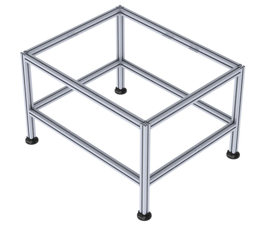
While I did make a few drawings, these do not show much in the way of construction, hence there is not much to show just yet. It will be simpler to build the thing and then make pictures.
So, until then…
XYZ Design
In the first post I wrote that I wanted a CNC-able area of at least 2 meters (X) by 40 centimers (Y). (2000mm x 400mm)
Unfortunately I was unable to find a ball-screw with a length of 2000mm for an affordable price. The ball-screw itself is not even that expensive, its the shipping that kills the idea. Some suppliers charge more for shipping than the ball-screw itself costs.
The longest I have been able to find is 1700mm which, including shipping, still costs me just over 150 euro’s (including two equal length sliders). Still way better than prices of over 400 euro’s for a 2000mm ball-screw (also incl. shipping, excl. sliders). Travel will not be quite 1700mm though, as the sliders are also 1700 mm and I will need about 200mm for the Y-stage.
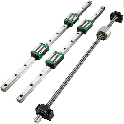
On the other hand, for the Y axis I was able to keep costs down and still manage a total travel of about 550-600mm. (Sliders are 700mm)
I have not decided on the Z-axis yet. I will probably go for a total travel of 100mm maybe 150mm. But I will first await arrival of the X and Y axis to check on their suitability for my purposes.
That remains a sour point: while this stuff is sold for CNC purposes, I have no experience with the sliders and spindle, and do not know how accurate the cutting tool will be able to trace out (repeatable) patterns. I hope that I will be able to achieve 0.1mm accuracy, but I don’t have any guarantees. Before selecting a Z-axis I will have to wait and see how well the X and Y axis perform to know how much effort/cost I should sink in the Z-axis.
Since it will be another two to three weeks before I receive the HW, I will have time to look at other stuff. For example the construction details of the XYZ stages and the table on which the machine should stand.
Given that the axis themselves will be 1700mm X 700mm, the table will need to be slightly bigger, something like 1800mm x 800m. The table height for normal work-surfaces is also about 800mm.
The table should be sturdy enough, but also dampen the higher frequencies from the stepper motors. But most of all, the sable should not sag at all in the middle where the wood to be cut will be placed.
Another issue is the construction of the X and Y stages. For the X axis I will be using two 20mm wide sliding rails and a ball-screw. These will be mounted on a (ply) wooden plate. The plate itself will be stiffened to the point that sag is so small to be virtually impossible to measure.
For the Y axis I will also be using two pieces of plywood mounted at 90 degrees to each other. Several other triangular pieces will be used squared to the two pieces to keep the angle between them at 90 degrees. On the vertical side I will mount rails similar to the X-axis, but only 12mm wide.
Using wood may not seem obvious, but I do not believe its as bad as we might think if the wood is plywood, waterproof and sealed correctly. I have some plywood constructions that retain their original shape even after years.
However that is not the main reason for choosing (ply)wood. The main reason is that I currently have no possibility to drill metal with sufficient accuracy to create a metal construction. With the XY axis in place I will have that capability, thus if the wood becomes too much of a problem I can at least build an all-metal CNC with the wooden CNC.
And lastly, since it may take a while before the hardware of the CNC is operational, I will start creating the first plans for cutting. One of my other blogs is about building a CL-415 RC-model, and that model is the first thing I want to build with the CNC. But I only have paper plans, which have to be converted into G-code. This is the perfect time to start on that.
I have decided to blog about creating the G-code on this blog, as RC-modellers may not be interested enough in this aspect. And detailing the steps taken may help others with similar interest.