A rectangle
FreeCAD can generate G-code. This is one of the most important aspects for choosing FreeCAD.
I did follow a FreeCAD tutorial that created just about the shape I wanted for testing the movements of the electronics. But unfortunately I cannot find it again.
So instead I will recommend following a few tutorials until you get the hang of it. There are probably youtube tutorials as well, I did not search for them.
Next we have to define the shape for the test: it will be a rectangle of 16x32mm with a thickness of 8mm. In the top of this rectangle a rectangular pocket will be made of 8x16mm with a depth of 4mm.
Like this:
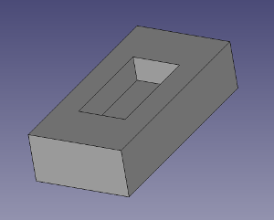
Once this shape is defined, the Path Walktrough for the impatient details the steps needed to create the G-code file.
You can see the results in a simulation in FreeCAD itself.
When done and satisfied with the results in the simulator write the G-code to a file using the extension gcode and store this on an SD-card. Then switch to the breadboard.
Switch on, and insert the SD-card. The menu on the LCD now displays that a media card has been inserted and the menu on the next page (press the button once) shows extra items, among which a Print from media, select this and select the file that must be printed. On the next screen, confirm that it should start printing. The steppers will start moving until ready. While the operation is ongoing a progress bar is shown.
So far so good. The steppers show approximately the expected behaviour with respect to sequence of events. But they do not show the appropriate rotation yet. This was to be expected as I have not yet configured V1-engineering Marlin for my breadboard.
That is next on my list.